
Three Phase Electrical Wiring Installation in Home NEC & IEC Tutorial
Zambia. 400 V. 50 Hz. 4. Zimbabwe. 400 V. 50 Hz. 3, 4. This is a chart which provides an overview of the three-phase voltages and frequencies in use in all countries around the world.
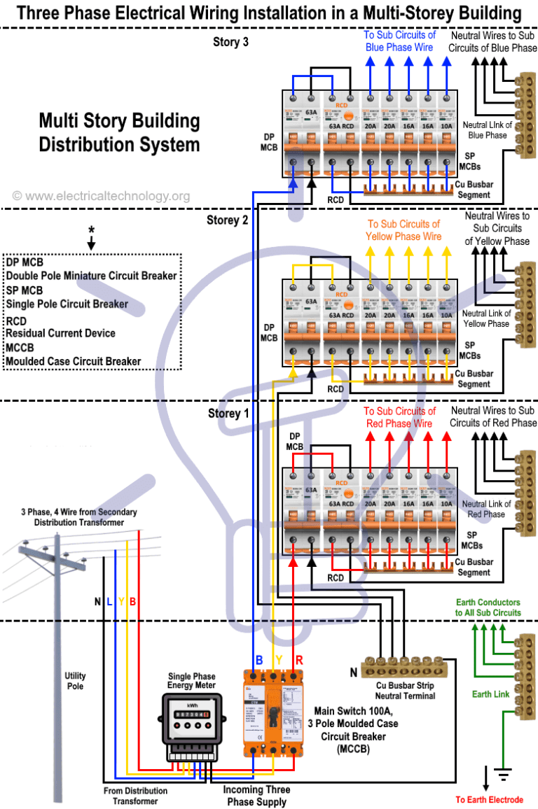
Three Phase Electrical Wiring Installation in a MultiStory Building
The calculator is designed to accept the total line voltage and current of the combined three cables. The equation for the area of a single wire is modified to: A = \frac {\sqrt 3 I \varrho L} {V} A = V 3I ϱL. The factor of \sqrt 3 3 is needed to convert between the system's phase current and line current.
3 phase wye wiring
The three-phase system has four wire, i.e., the three current carrying conductors and the one neutral. The cross section area of the neutral conductor is half of the live wire. The current in the neutral wire is equal to the sum of the line current of the three wires and consequently equal to √3 times the zero phase sequence components of current.
The Importance of Neutral Wire in 3Phase Systems Technical Articles
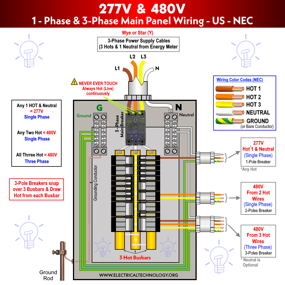
What is Three Phase & Single Phase Power? Why Do We Need Three Phase Power Supply? 3-Phase & 1-Phase Voltage Levels in the US - NEC 3-Phase & 1-Phase Voltage Levels in the UK, EU - IEC Requirements for Three Phase Wiring Installation How to Wire Three Phase Main Distribution Board? Three Phase Electrical Wiring Installation Diagrams - US -NEC
480 Volt 3phase Wiring
Three-phase power is a three-wire ac power circuit with each phase ac signal 120 electrical degrees apart. Residential homes are usually served by a single-phase power supply, while commercial and industrial facilities usually use a three-phase supply.
3 Phase Wiring Diagram Plug
A three-wire three-phase circuit is usually more economical than an equivalent two-wire single-phase circuit at the same line-to-ground voltage because it uses less conductor material to transmit a given amount of electrical power. [3]
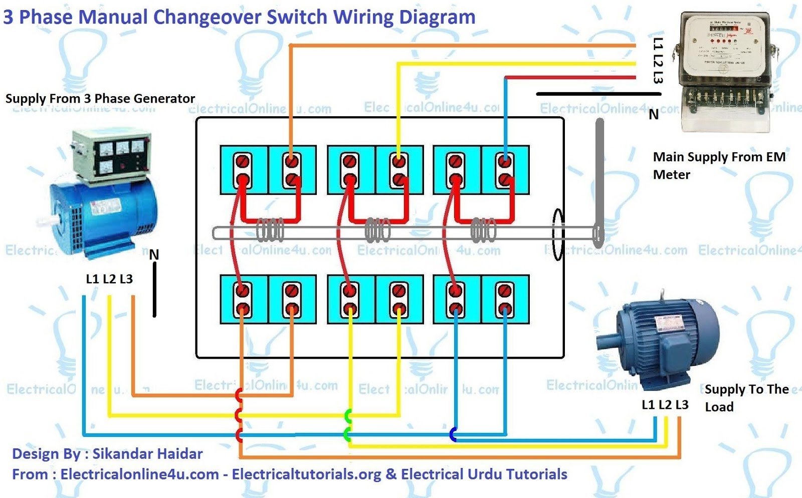
3 Phase Manual Changeover Switch Wiring Diagram For Generator Electrical Online 4u
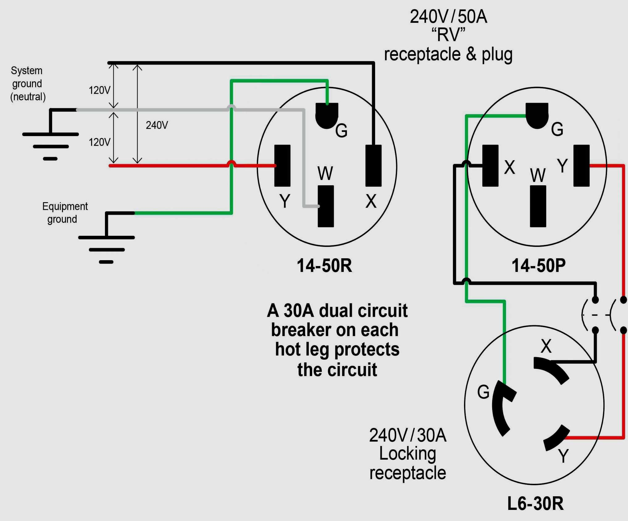
Three Phase Three-phase power is supplied by four wires. Three hot wires carrying 120 volts of electricity and one neutral. Two hot wires and the neutral run to a piece of machinery requiring 240 volts of power. Three-phase power is more efficient than single-phase power.

Addison 3 Phase Wire, Addison Cable Private Limited ID 20390093530
Elementary three-wire three-phase alternator, showing how the phases can share only three transmission wires. Each phase of a three-phase transformer has its own pair of windings, with a shared core. Balanced loads Generally, in electric power systems, the loads are distributed as evenly as is practical among the phases.
200V 3 Phase Wiring Diagram Diagram Database
What is Delta Connection (Δ)? Delta or Mesh Connection (Δ) System is also known as Three Phase Three Wire System (3-Phase 3 Wire) and it is the most preferred system for AC power transmission while for distribution, Star connection is generally used.. In Delta (also denoted by Δ) system of interconnection, the starting ends of the three phases or coils are connected to the finishing ends of.
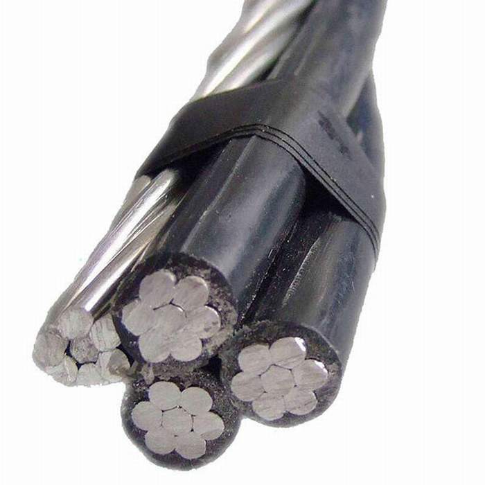
Aluminum Conductor 3 Phase Wire XLPE Insulation ABC Cable jytopcable
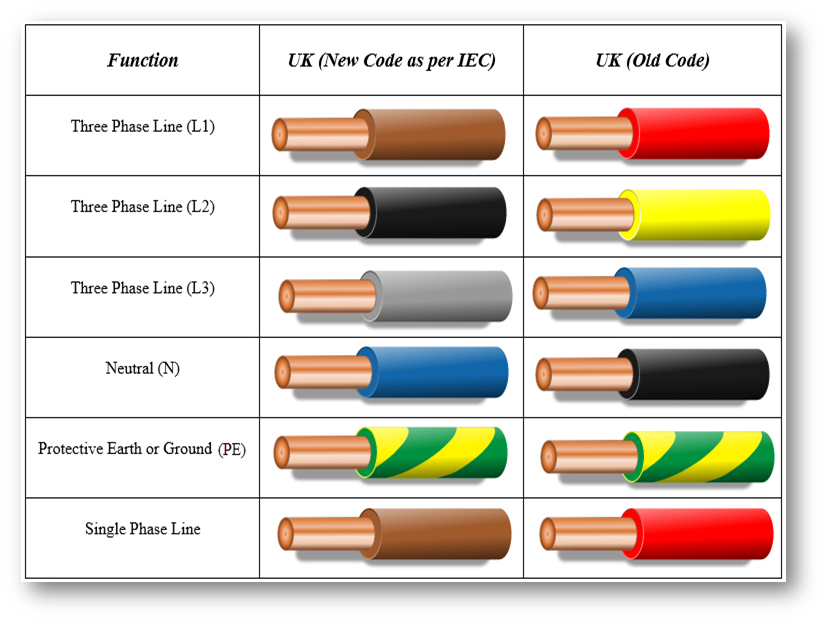
Wiring Color Codes - NEC Electrical Standards & 3-Phase Wire color coding Improving electrical safety, one wire at time Electricity powers the world. It lights up, turns on and charges nearly everything we touch, all with the flick of a switch.
HUBBELL WIRING DEVICEKELLEMS 100 Amp, 3Phase Nylon Watertight Pin and Sleeve Plug, Red 4HD02
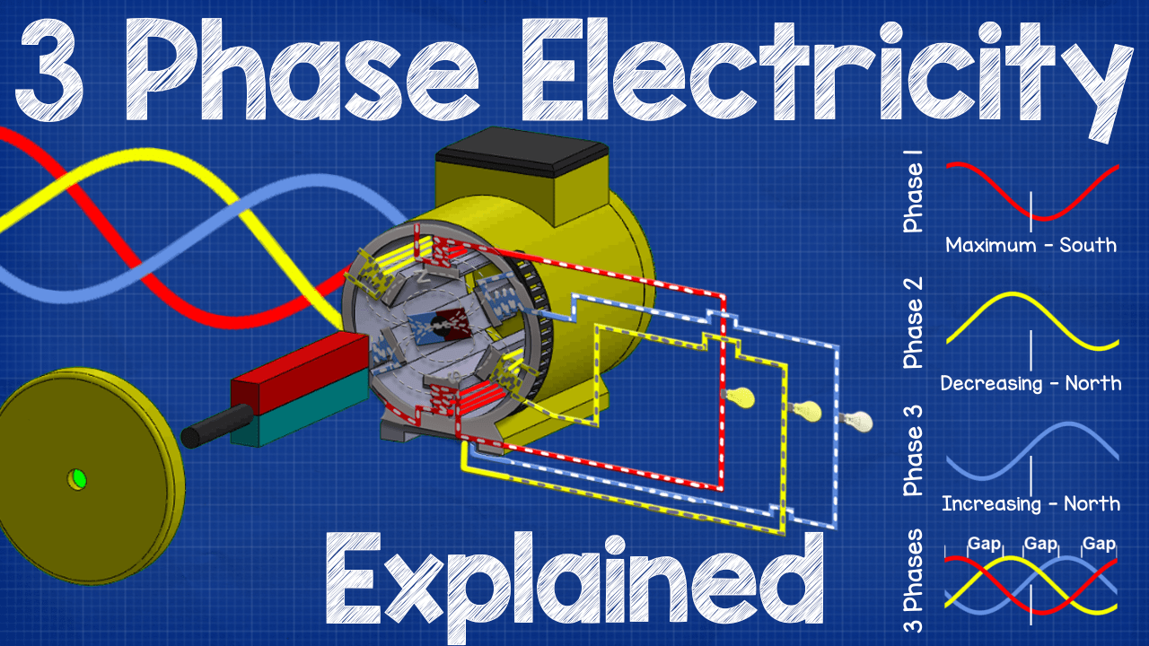
Three-phase power can be defined as the common method of alternating current power generation, transmission, and distribution. It is a type of polyphase system and is the most common method used by electric grids worldwide to transfer power. Three-Phase Power Explained Watch on Watch the Video More Raritan Resources Transcript:

Dart Wiring 208 Volt Single Phase Wiring Diagram
In a three-wire, three-phase system, let the rms voltage between each wire and the ground (the ground is often a grounded wire, making it a four-wire system) be V ′, the current in each wire be I, and the phase angle between the two be ϕ. Because there are three phases, the total power transmitted is as follows: (1.2)

3 Phase 4 Wire System Your Electrical Guide
Three-phase Three-Wire Connection (Three Wattmeter Method) Although only two wattmeters are required to measure total power in a three-wire system as shown earlier, it is sometimes convenient to use three wattmeters. In the connection shown in Figure 13, a false neutral has been created by connecting the voltage low terminals of all three.

3 phase motor wiring Wire, Diagram, Motor
Three-phase systems can be three-phase three wire or three-phase four wire systems. Three-phase 3 line connection consist of three phase conductors and is employed only where there is no requirement for connecting phase to neutral loads. These connections can be star or delta depending on the secondary of the distribution transformer.

230v 3 Phase Motor Wiring Diagram
Three-phase, four-wire "Y" connection uses a "common" fourth wire. The three conductors leading away from the voltage sources (windings) toward a load are typically called lines, while the windings themselves are typically called phases.

3 Phase Wire 1.5M Artisan Supplies
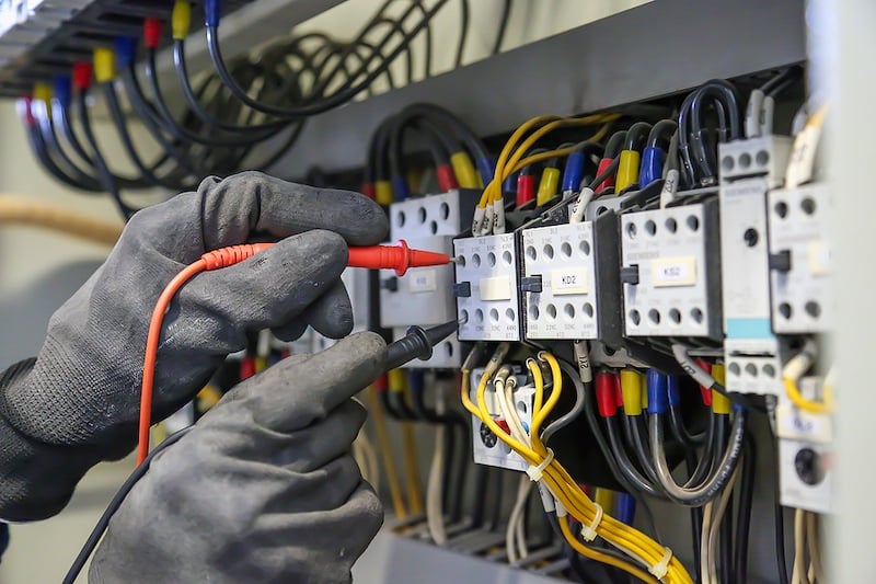
March 21, 2021 by David Peterson Learn about the importance of wiring in 3-phase systems and how to complete this wiring in various industrial scenarios and control cabinets. Every industrial electrician or engineer knows about 3-phase power and the wiring involved.